Thursday, 22 September 2011
Friday, 16 September 2011
Surface Modeling | Graphics Designing
Surface Modeling
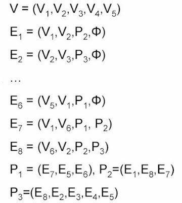
Several methods are available to model surfaces– Polygon meshes
• Surface is represented as a set of bounded planar surfaces
– Parametric polynomial curves
• Surface is defined by 3 equation in a parameter, t, one for each principal axis (x, y, z)
– Parametric bivariate polynomial surface patches
• Similar to parametric polynomial curves but this time each equation has two variables
– Quadratic surfaces
• Surface is implicitly defined by an equation f(x, y, z) = 0
Tuesday, 2 August 2011
The U-V-N System
The camera plane is defined by 3 parameters:
- View Reference Point (VRP): A point (in the world frame) indicating the center of the camera's image plane. This specifies the position of the camera in space.
- View Plane Normal (VPN): A unit vector perpendicular to the camera's image plane. This specifies the orientation of the camera.
- View Up (VUP): A vector indicating the up direction (in world coordinates) for the camera.
3d Viewing in Computer Graphics
3d Viewing in Computer Graphics
Two stages to the 3D to 2D transformation
- First a clipping,
- Then a projection.
The view volume of a perspective projection is the infinite volume defined by the combination of the PRP and the view window, which defines a pyramid. This can be contrasted to the view volume for a parallel projection which gives an infinite parallelepiped.
Saturday, 30 July 2011
Thursday, 28 July 2011
Perspective Projections | OpenGL
Perspective Projections
1. The visual effect of the perspective projection is similar to the human visual system known as perspective foreshortening i.e. the size of perspective projection object varies inversely with the distance of the object from COP.2. Perspective projection does not preserve parallel lines.
3. Vanishing Point
Any set of parallel lines that are not parallel to projection plan appear to converge to a point called vanishing point.
* In this case lines parallel to x and y do not converge, only lines parallel to z do so
* One point perspective projection of a cube
* A two point perspective projection of a cube
Tuesday, 26 July 2011
Parallel Projections | OpenGL
Parallel Projections
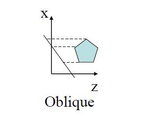
In case of parallel projection instead of having COP we have direction of projection (DOP), so the perspective projection whose COP is at infinity becomes parallel projection.In parallel projections, the lines projecting from an object onto the image plane are parallel.
Two parallel projection systems:
1. Orthographic projection
2. Oblique projection
In these the projection plane is normal and direction of projection differ.
Its major types are:
– Cabinet
– Cavalier
Monday, 18 July 2011
Projections
Projection
Projection is the change in coordinate system and that is usually from 3D to 2D.
Projectors
The projection of a 3D object is described by straight `projection rays' (called projectors).
Types Of Projection
Projections can be divided into two basic
types
1. Perspective
2. Parallel
• The distinction between two is on the relation of COP and projection plane.
• If distance of one projector to another is finite then it is perspective projection otherwise it is parallel.
Perspective Projection
Parallel Projection
Projection is the change in coordinate system and that is usually from 3D to 2D.
Projectors
The projection of a 3D object is described by straight `projection rays' (called projectors).
Types Of Projection
Projections can be divided into two basic
types
1. Perspective
2. Parallel
• The distinction between two is on the relation of COP and projection plane.
• If distance of one projector to another is finite then it is perspective projection otherwise it is parallel.
Perspective Projection
Transformations Change Coordinate Systems
Transformations Change Coordinate Systems
One useful coordinate system transformation is given by:
One useful coordinate system transformation is given by:
Which transforms from a left handed to a right handed coordinate systems (and is its own inverse)
Rotation Direction
Rotation Direction
Which way is +ive rotation1. Look in –ve direction (into +ve arrow)
2. Counter Clock Wise is +ve rotation
Saturday, 16 July 2011
Composing Transformation
Applying several transforms in succession to form one overall transformation is known as Composing Transformation.
(M3 x (M2 x (M1 x P ))) = M3 x M2 x M1 x P
1. Transformation products may not be commutative.
A x B != B x A
2. Some cases where A x B = B x A
A B
translation translation
scaling scaling
rotation rotation
uniform scaling rotation
(sx = sy)
3. Rotation and translation are not commutative.
Example :
Suppose we wish to reduce the square in the following image to half its size and rotate it by 45° about point P.
We need to remember that that scaling and rotation takes place with respect to the origin.
1– Translate square so that the point around which the rotation is to occur is at the origin
2– Scale
3– Rotate
4– Translate origin back to position P
Sunday, 10 July 2011
Window to Viewport Transformation
To display the appropriate images on the screen (or other device) it is necessary to map from world coordinates to screen or device coordinates.
This transformation is known as the window to viewport transformation, the mapping from the world coordinate window to the viewport (which is given in screen coordinates)
This transformation is known as the window to viewport transformation, the mapping from the world coordinate window to the viewport (which is given in screen coordinates)
In general the window to viewport transformation will involve a scaling and translation as in figure below here the scaling in non-uniform (the vertical axis has been stretched).
Friday, 29 April 2011
Computer Graphics and Geometric Transformations
2D Transformations
2D computer graphics is the computer-based generation of digital images—mostly from two-dimensional models.There are three types of transformations that are essential in computer graphics
1-Translation
Moving an object to a new location by adding to objects x and y co-ordinates.
2-Scaling
Changing the size of the object.This can be uniform where both dimensions are re-sized by same factor or non-uniform.
3-Rotation
Object is rotated around the origin by specified angle.
Homogeneous Transformations
In order to represent a translation as a matrix operation we use 3 x 3 matrices and pad our points to become 1 x 3 matrices.
Wednesday, 27 April 2011
Lighting
- Direction light source
- Position light source
- glLightfv( Light#, Attribute, …)
- GLfloat position[] = {10, 10, 10, W} glLightfv(GL_LIGHT0, GL_POSITION, position) If (W) is zero the position is treated as a direction (a 1x3 vector); otherwise, it is treated as a position (a 1x4 vector)
- glEnable(GL_LIGTHING)
- glEnable(GL_LIGHT0)
Drawing in 3D
Depth buffer
Allows scene to remove hidden surfaces. Use glEnable(GL_DEPTH_TEST) to enable it.
1-glPolygonMode( Face, Mode )
Face: GL_FRONT, GL_BACK, GL_FRONT_AND_BACK
Mode: GL_LINE, GL_POINT, GL_FILL
2-glCullFace( Mode )
Mode: GL_FRONT, GL_BACK, GL_FRONT_AND_BACK
3-glFrontFace( Vertex_Ordering )
Vertex Ordering: GL_CW or GL_CCW
OpenGL States
On/off (e.g., depth buffer test)
- glEnable( GLenum )
- glDisable( GLenum )
- Examples:
- glEnable(GL_DEPTH_TEST);
- glDisable(GL_LIGHTING);
Mode States
- Once the mode is set the effect stays until reset
Examples:
glShadeModel(GL_FLAT) or glShadeModel(GL_SMOOTH)
glLightModel(…) etc.
glShadeModel(GL_FLAT) or glShadeModel(GL_SMOOTH)
glLightModel(…) etc.
OpenGL Primitives
Drawing two lines
glBegin(GL_LINES);
glVertex3f(_,_,_); // start point of line 1
glVertex3f(_,_,_); // end point of line 1
glVertex3f(_,_,_); // start point of line 2
glVertex3f(_,_,_); // end point of line 2
glEnd();
We can replace GL_LINES with GL_POINTS, GL_LINELOOP, GL_POLYGON etc.
glBegin(GL_LINES);
glVertex3f(_,_,_); // start point of line 1
glVertex3f(_,_,_); // end point of line 1
glVertex3f(_,_,_); // start point of line 2
glVertex3f(_,_,_); // end point of line 2
glEnd();
We can replace GL_LINES with GL_POINTS, GL_LINELOOP, GL_POLYGON etc.
OpenGL Syntax
All functions have the form: gl*
1-glVertex3f() – 3 means that this function take three arguments, and f means that the type of those arguments is float.
2-glVertex2i() – 2 means that this function take two arguments, and i means that the type of those arguments is integer.
All variable types have the form: GL*
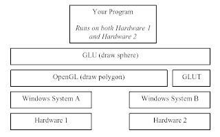
1-In OpenGL program it is better to use OpenGL variable types (portability)
2-GLfloat instead of float
3-Glint instead of int
OpenGL Order of Operations
Construct shapes
1-Vertices
2-Edges
3-Polygons
Use OpenGL to:
1-Arrange shape in 3D (using transformations)
2-Select your vantage point (and perhaps lights)
3-Calculate color and texture properties of each object
4-Convert shapes into pixels on screen
1-Vertices
2-Edges
3-Polygons
Use OpenGL to:
1-Arrange shape in 3D (using transformations)
2-Select your vantage point (and perhaps lights)
3-Calculate color and texture properties of each object
4-Convert shapes into pixels on screen
Overview of an OpenGL Program
Main
1-Open window and configure frame buffer (using GLUT for example).
2-Initialize GL states and display (Double buffer, color mode, etc.).
Loop
1-Check for events
a)if window event (resize, unhide, maximize etc.)
b)modify the viewport and Redraw
c)else if input event (keyboard and mouse etc.)
d)handle the event (such as move the camera or change the state) and usually draw the scene
Redraw
1-Clear the screen (and buffers e.g., z-buffer)
2-Change states (if desired)
3-Render
4-Swap buffers (if double buffer)
Sutherland-Hodgman Polygon Clipping
Sutherland-Hodgman Polygon Clipping
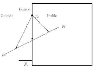
1-The Sutherland-Hodgman polygon clipping algorithm clips polygons against convex clipping windows.
2-It does so by clipping the subject polygon against each clip edge producing intermediate subject polygons.
3-The Sutherland-Hodgman may produce connecting lines that were not in the original polygon. When the subject polygon is concave (not convex) these connecting lines may be undesirable artifacts.
Polygon Clipping
Polygon clipping differs from line clipping in several respects:
1-The input to the clipper is a polygon, which for simplicity we will view as a list of n >= 3 vertices (v0; v1; : : : ; vn-1).
2-The output from the clipper is one or more polygons
3-The clipping process may generate vertices that do not lie on any of the edges of the original polygon.
4-Complex polygons (that is, non-convex) may lead to strange artifacts.
2D Raster Algorithms
1-DDA Algorithm
The digital differential analyzer (DDA) samples the line at unit intervals in one coordinate corresponding integer values nearest the line path of the other coordinate.
Major deficiency in the above approach :
1-Uses floats
2-Has rounding operations
2-Bresenham’s Line drawing Algo
An accurate, efficient raster line drawing algorithm developed by Bresenham, scan converts lines using only incremental integer calculations that can be adapted to display circles and other curves.
Display Primitives | Computer Graphics
Computer Graphics Display Primitives
1- Graphics (modeling & rendering) primitives2- Points, lines, polygons
3- Various line-drawing algorithms
4- DDA and Mid-point Line Drawing Algorithms
5- Circles drawing
6- Mathematical concepts
a)line equations
b)parametric representation, implicit
7- Functions, vectors and matrices
Tuesday, 26 April 2011
Computer Graphics Design
Computer Graphics Design
Mechanism for video display1-CRT principle and structure
2-Frame buffer
3-Dot size, resolution
4-Refresh rate
5-Shadow masking in colored CRTs
Logic structure for other display
1-LCD
2-Plasma display
Conceptual Models for CG
1-Application Model
2-Application Program
3-Graphics System
I/O Devices
1-Printers and Plotters
Key Components of a Computer Graphics Design System
1-Video controller2-Display processor
Subscribe to:
Comments (Atom)


